Designing a Complete Instrument Loop for Process Plants
Every component, every decision — from process connection through device mounting, tubing support, cable routing, and support structure. A reference guide for instrument and electrical engineers.
Overview
The instrument loop as a system.
An instrument loop is the complete chain of hardware, wiring, and tubing that connects a process measurement point to the control system. In a refinery, LNG facility, or power plant, a single instrument loop might measure pressure at a vessel nozzle, transmit that measurement as a 4-20mA signal through instrument cable to a junction box, route that signal to a marshalling cabinet, and ultimately deliver a process variable to the distributed control system that the operator uses to manage the unit.
A large process plant contains thousands of individual instrument loops. Each one requires the same set of installation components: something to protect the instrument from the process fluid, something to mount the instrument, something to support the impulse tubing between the process tap and the instrument, and something to route the cable from the instrument to the control system. The selection and specification of those components — and the interactions between them — determines whether the instrument loop performs reliably for the life of the facility or requires constant maintenance.
This page walks through a complete instrument loop installation from process tap to junction box, documenting every decision and every TechLine component that supports it. It is written for the instrument engineer at an EPC firm who is specifying an instrument loop for a new process unit, and for the instrument technician at an operating plant who is designing a retrofit or modification.
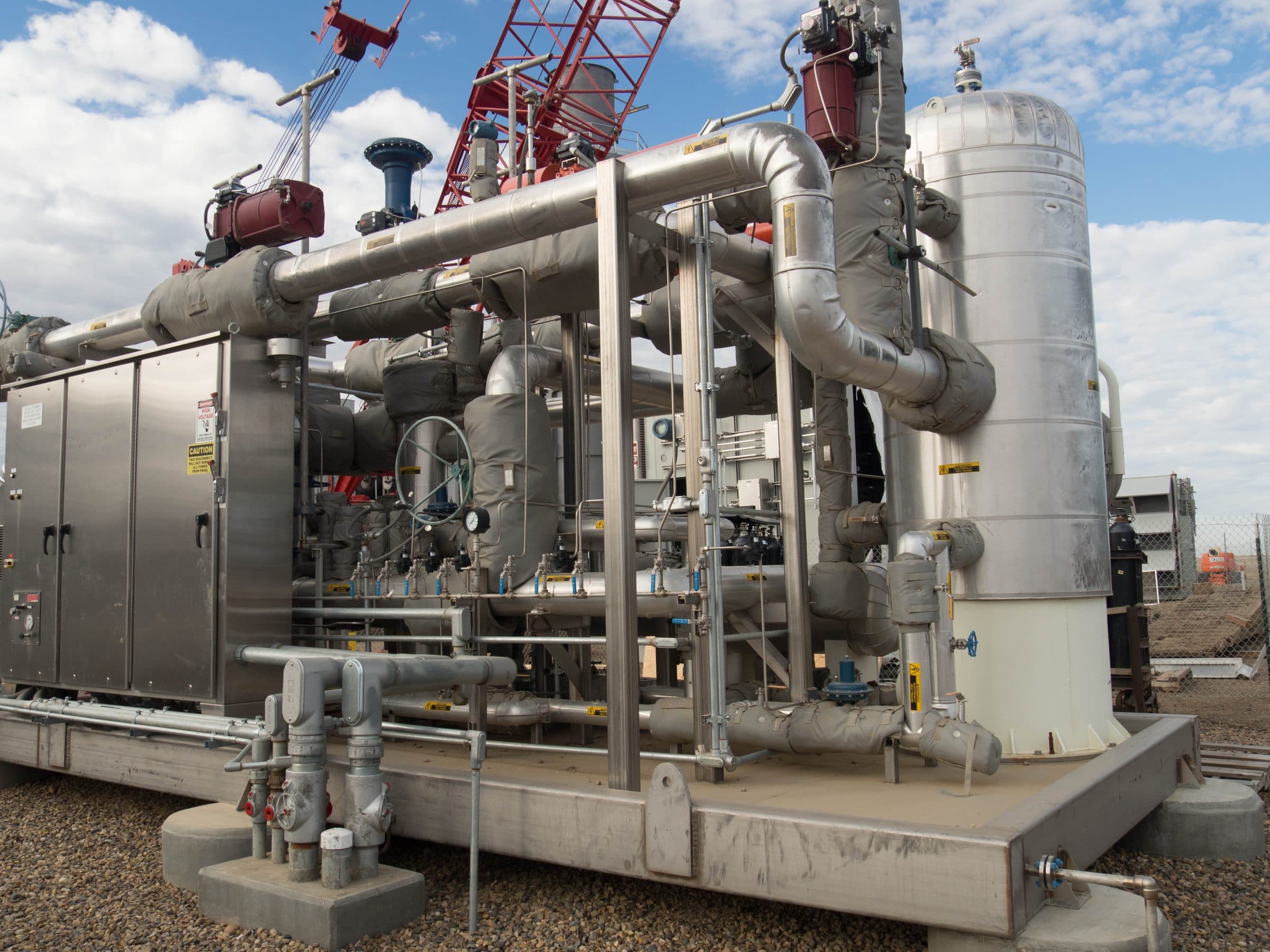
Components
Every component from process tap to junction box.
A complete instrument loop installation involves six categories of hardware. Each category has a defined role, a set of selection criteria, and a set of failure modes when the wrong product is specified for the application.
1.Process connection and protection hardware
The condensate chamber or seal pot sits between the main process line and the instrument. Its job is to protect the instrument from process conditions — steam, condensate, corrosive vapors, and viscous fluids — that would damage the measurement device or cause calibration drift. In steam service, the condensate chamber establishes and maintains a liquid column between the steam header and the transmitter, protecting the transmitter diaphragm from direct steam contact and temperature extremes. In gas service, the chamber traps condensate and foreign material that would otherwise accumulate in the impulse line and affect measurement accuracy.
The distribution manifold, where used, supplies instrument air or purge gas from a single header to multiple instruments. Manifolds simplify the instrument air distribution infrastructure, reduce the number of individual connections to the main supply, and provide isolation valves at each instrument connection for maintenance without system shutdown.
2.Impulse tubing support
The impulse tubing between the process tap and the instrument — typically ¼" or ⅜" stainless steel tubing — needs to be supported, organized, and protected along its run. Perforated angle and channel tray serve this function. The tubing runs are organized in the tray, supported at the required spacing, and protected from mechanical damage by the tray's solid side rails.
Perforated angle is used for single-plane straight runs. Channel tray is used for runs that need more organization or where multiple tubing runs share the same pathway. Clamps secure individual tubes or tube bundles to the tray structure at the required support intervals.
3.Field device mounting
The instrument itself — pressure transmitter, temperature element, flow meter, level instrument, or analyzer — needs a mount that holds it in the correct position, resists the mechanical loads of the process environment (vibration, wind, and thermal expansion), and allows maintenance access without disturbing adjacent equipment.
Single instruments mount on instrument stands — pipe-mounted, floor-mounted, or wall-mounted depending on the physical arrangement of the process equipment. Multiple instruments in the same area mount on ModRack or FixedRack structures that consolidate multiple devices onto a single support system, reducing the number of individual stand foundations and simplifying the maintenance access layout.
4.Instrument cable routing
The instrument cable — ITC, PLTC, or TC-rated, depending on the application — routes from the instrument junction head or terminal block through the field to a local junction box. This cable run needs a protected, organized, accessible pathway that meets NEC Article 392 requirements and survives the process plant environment for the life of the facility.
Snap Track channel cable tray is the primary cable routing system for this portion of the instrument loop. The tray provides physical protection for the cable, organizes multiple cable runs in a maintainable pathway, and provides the code-compliant system documentation that AHJs require.
5.Support structure for tray and tubing
The tray and tubing runs need structural support — hangers, brackets, strut, and post bases — at intervals determined by the load and span data for the specific tray product. For Snap Track, support spans up to 18 feet are achievable depending on load, reducing the number of hangers required compared to shorter-span competitive products.
Perforated angle fittings — elbows, tees, and crosses — handle direction changes in the tubing support structure without field fabrication. Strut and strut fittings provide the structural framework that hangs from overhead steel or mounts from grade.
6.Fasteners and clamps
Every connection in the instrument loop installation — tubing to tray, tray to support, stand to foundation — requires the right fastener or clamp. Tubing clamps secure individual impulse tubes and tube bundles to the support structure at the required spacing. Threaded fasteners connect structural components. Grating fasteners attach support members to open grating decks where floor mounting is through grating rather than concrete.
Clamp selection depends on tube OD, clamp spacing, and environmental requirements. In corrosive environments, stainless steel clamps are standard. In vibration-prone installations, cushion clamps reduce the stress concentration at the clamp contact point.
Worked Example
From process tap to junction box — a worked example.
The following describes a complete instrument loop installation for a gauge pressure transmitter on a steam line in a Gulf Coast refinery. This is one of the most common instrument loop configurations in process plants and illustrates every installation decision the engineer needs to make.
The Application
Step 1.Process connection — condensate chamber selection
Steam service requires a condensate chamber between the process tap and the transmitter. The chamber establishes a liquid condensate column that protects the transmitter diaphragm from direct steam contact and thermal shock.
The chamber ships with a hydrostatic pressure test certificate per ASME Section VIII Division 1, UG-99. Welding per ASME Section IX. The process connection from the nozzle to the chamber uses a 3-valve manifold — block, block, and equalize — to allow the chamber to be isolated and drained for transmitter maintenance without shutting down the process tap.
Step 2.Impulse tubing support — perforated angle selection
The impulse tubing run from the condensate chamber to the instrument stand is typically short — 2 to 6 feet in most process plant configurations. For this example, the tubing runs 4 feet from the chamber to the transmitter, supported on perforated angle mounted to the process structure.
Step 3.Field device mounting — instrument stand selection
The pressure transmitter mounts on a 2" pipe stand adjacent to the vessel nozzle. The mounting arrangement is a standard pipe mount stand with a 2" pipe nipple extending from the main pipe structure.
The stand provides a rigid, vibration-resistant mount that holds the transmitter in the correct position for process connection and maintenance access. Stock items ship within 24 hours.
Step 4.Instrument cable routing — Snap Track selection
The 75-foot cable run from the transmitter to the junction box routes through a process area instrument corridor shared with other instrument loops in the same area.
Fill calculation
8 × 0.096 in² = 0.77 in² total fill
2" Snap Track allowable fill: 0.80 in² per NEC 392.22
✓ 8 cables fit within the 2" tray fill capacity.
Support points at 18-foot intervals reduce hanger count significantly compared to conduit (10-foot maximum support spacing for 1" RMC per NEC 344).
Step 5.Assembly — what goes together and in what order
The correct installation sequence for this instrument loop:
- Install Snap Track support structure — hangers and brackets on the overhead steel and at the junction box.
- Run Snap Track from junction box to instrument area, including the elbow fitting at the direction change.
- Install instrument stand at the process pipe.
- Install condensate chamber at the process nozzle, with 3-valve manifold.
- Run impulse tubing from condensate chamber to instrument stand mounting point, securing to perforated angle support with tubing clamps.
- Mount transmitter on instrument stand.
- Connect impulse tubing to transmitter.
- Pull instrument cable from junction box through Snap Track to transmitter terminal head.
- Terminate cable at transmitter and at junction box.
- Install bonding jumper on Snap Track for electrical continuity.
- Complete loop check and calibration.
Reference
Complete instrument loop component checklist.
Use this checklist when specifying a complete instrument loop installation. Every category represents a product decision that affects the long-term reliability and maintainability of the installation.
Process Connection & Protection
- Condensate chamber / seal pot — size, material, wall thickness, port configuration
- Distribution manifold (if instrument air supply required)
- 3-valve or 5-valve manifold for chamber isolation
- Process connection hardware (nipples, flanges, fittings)
Impulse Tubing Support
- Perforated angle or channel tray for tubing runs
- Tubing clamps — size matched to tube OD, material matched to environment
- Fittings for direction changes (elbows, tees)
- Support hardware (beam clamps, U-bolts, strut)
Field Device Mounting
- Instrument stand type (pipe mount, floor mount, wall mount, U-bolt mount)
- Material (galvanized, aluminum, 304SS, 316SS)
- Mounting hardware
- ModRack or FixedRack if multiple instruments in one area
Instrument Cable Routing
- Snap Track size (2", 4", or 6") based on cable count and fill calculation
- Material (aluminum standard; 316SS for severe corrosive service)
- Straight sections — quantity based on run length
- Fittings — elbows, tees, waterfall, conduit adapters as required
- Support hardware — hangers, brackets, strut at correct span intervals
- Bonding jumper for electrical continuity
Fasteners & Clamps
- Threaded fasteners — material matched to environment
- Grating fasteners if mounting through grating deck
- Hold-down clamps for cable in tray
- Additional tubing clamps as required
Documentation
- Condensate chamber ASME pressure test certificate
- Snap Track UL classification documentation
- Instrument stand material certification if required by project spec
- Loop drawing showing all components and part numbers
Avoid These Mistakes
What goes wrong and how to avoid it.
Undersizing the cable tray.
The most common mistake in instrument cable routing is specifying tray size based on the current cable count without accounting for future additions. Process plants add instruments throughout their operating life — during turnarounds, as process modifications are made, and as control system upgrades add measurement points. Specifying 4" tray where 2" would technically fit today avoids the cost of adding parallel trays later.
Wrong condensate chamber material for the service.
Carbon steel chambers in corrosive process service — even outdoor atmospheric exposure in Gulf Coast environments — corrode faster than the process plant lifecycle. 316SS is the conservative specification for Gulf Coast outdoor service regardless of process fluid. For high-temperature steam service, verify that the chrome alloy grade matches the operating temperature — P11 for moderate high-temperature service, P22 or P91 for advanced high-temperature applications.
Insufficient support spacing documentation.
Tray support spacing affects the structural integrity of the cable management system throughout the facility's life. Using the published Snap Track load data to document the design support span for each installation — and recording it in the loop documentation — ensures that future maintenance activity doesn't inadvertently remove supports that are structurally necessary.
Mixing cable types in tray without fill recalculation.
Adding cables to existing tray without recalculating fill against NEC 392.22 allowable fill capacity is a compliance issue and an operational risk. The continuous hole pattern in Snap Track makes adding cables easy — which is a feature, not an invitation to ignore fill limits.
Instrument stand material mismatch.
Specifying galvanized instrument stands in a 316SS condensate chamber installation creates a material discontinuity that accelerates galvanic corrosion at the connection points. Match stand material to chamber material in corrosive environments.